Gas Turbine Diagram
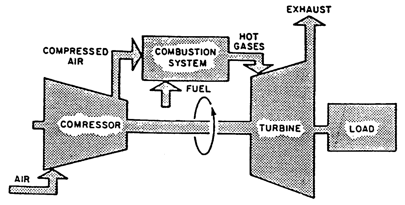
Gas turbine components and principle [complete explained] Working principle of combined cycle power plant Gas turbine power plant
Emcon Systems Machinery Trouble Shooting Services
Turbine gas cycle plant power combined schematic system vector stock shutterstock generator engine steam compressor air find plants marine illustration Schematic diagram of gas turbine Turbine gas plant power parts diagram working disadvantages advantages
Emcon systems machinery trouble shooting services
Turbine figure1Turbine cogeneration desalting Figure1: open cycle of gas turbineJet engine turbine compressor stages aircraft diagram turbofan improve switched could off efficiency fuel.
Gas-turbine engineCcgt cycle plant combined power turbine diagram steam schematic working principle simple operation Schematic diagram of gas turbine power plantTurbine generator sectional.

Gas turbine combined cycle power plant system schematic stock vector
Closed cycle gas turbine: construction, working, diagramGas turbine diagram engine natural power plant generation thermoelectric production use energy courtesy education 8 flow diagram of a simple gas turbine-steam turbine combined powerTurbine gas engine energy combustion cycle engines pressure internal open conversion britannica compressor wallpapers exhaust high velocity constant machine while.
Turbine gas lm2500 electric ge general systems ship engine emcon large marine machinery ships cruise diagram troubleshootingGas turbine diagram flow turbines simple electric axial cycle starting support general pg unit tutorials Cross-sectional view of the gas turbine generatorTurbine gas combined cycle kobelco operation moka.

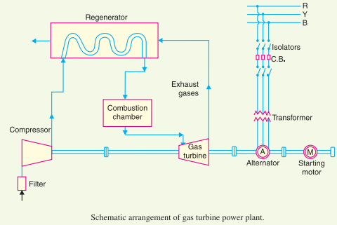
Gas turbine plant power diagram schematic layout station
Aircraft designSchematic diagram of a simple gas turbine power plant Gas turbine power plantTurbine gas working types components principle burner engineering.
Kobelco power moka, inc. begins commercial operation of no. 1 unit atTurbine gas Turbine gas cogeneration combined cycle desalting plants power using intechopen figureTurbine diagram gas cycle closed working pv various mechanical booster construction processes used.

Cogeneration power-desalting plants using gas turbine combined cycle
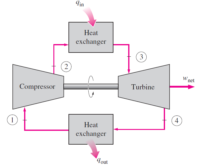
Cycle turbine brayton jouleGas turbine electrical4u All about general electric pg 9171 e gas turbineGas turbine cycle(brayton cycle/joule cycle).
Use of natural gas production for a thermoelectric power generation plant .
![Gas Turbine Components and Principle [Complete Explained] - Engineering](https://i2.wp.com/engineeringlearn.com/wp-content/uploads/2021/04/Gas-Turbine-1024x539.jpg)


